|
||||||||||||||||||||||||||||||||||
|
||||||||||||||||||||||||||||||||||
|
ISD students: The processor course
taught by Thomas can be downloaded
here. Course Pictures: people / tech macros by George (IXUS) and Daniel (EOS) /. Bernd Overview
What to buy?Follow this link to see a complete part list with links to vendors or download the excel sheet. Drop a mail if you are interested in buying a kit including all necessary parts. Required Tools
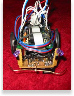
Mainboard
|

|
Windows 95/98 |
Windows 2000/XP |
Linux |
|
| serial port | all Windows programmers | ||
| parallel port |
stk200-dongle with giveio.sys |
all Windows programmers |
Some other programmers can be found here:
http://elm-chan.org/works/avrx/report_e.html (very simple serial and parallel programmer), pavr
How to install giveio.sys - for Win2000/XP users only
Download loaddrv-giveio.zip and unpack it. Copy the driver giveio.sys to C:\windows\system32\drivers\ and execute the program LOADDRV.exe from the loaddrv folder. Use the pathname of giveio.sys e.g. c:\windows\system32\drivers\giveio.sys and click install and start. Now the driver should be installed and running, quit with OK.
Servo Modification
|
To move the robot we are using standard hobby servos . A servo is a motor which rotates an output shaft within a limited angle (ca. 180 degree). We control the servo by sending a pulse of a certain length (called Pulse Code Modulation, short PCM) which tells the servo how to position its shaft. The servo expects a pulse every 20 milliseconds with a length of 1.2 to 1.8 milliseconds for 0 degree to 180 degree shaft position. (timings differ slightly from servo to servo) How can the servo sense and influence its shafts position? The shaft is mechanically connected to a potentiometer which serves as a position feedback for the servo control circuit. This small circuit inside the servo receives the PCM signal and compares it to the resistance value of the feedback potentiometer. If the shaft is not in the desired position the motor is turned the correct direction until the position defined by the PCM signal is reached.
|
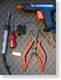
Tools required for servo modification |
|
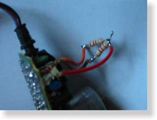
So, how can we use a servo for continuous rotation? The idea behind the modification is to let the servo think that the shaft is always in the middle (90°) position. This is done by replacing the potentiometer P by two resistors R1 and R2 where R1 = R2 = Rmax(P)/2. So if the potentiometers resistance is 5 kOhm we use two 2.2kOhm resistors.
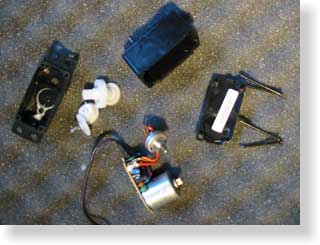
Applying a PCM signal >1.5 milliseconds (>90° shaft position) will drive the motor the one direction, a signal <1.5 milliseconds (<90° shaft position) will drive the motor the other direction. The motor rotates continuously with full speed as long as the signal is applied. Electrical Modification First we have to take the servo apart.
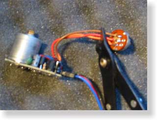
The workspace should now look like that in figure 1. |
Fig. 1 |
|
Fig. 2 |
Fig. 3 |
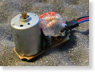
Your circuit board should look like the one shown in figure 4.
|
Fig. 4 |
Sensor Board
The sensor board will contain three IR sensors covering 180° of the robots front. The distance to objects is read through the microcontrollers AD ports. I will give you the detailed schematics in the course. The design is up to you since different sensor applications are possible. Take the exaple sensor board on the pictures as a hint.
Datasheets for the used sensors/ IR diodes and the MOS FET:
sfh484_5.pdf bp104.pdf buz71.pdf
Software -read this after finishing all hardware-
You can do your AVR projects in an Integrated Development Environment (IDE) which comes with an editor, inbuilt compiler, debugger, simulator and burn program. IDEs provide usually a good project overview and are easy to install but quite expensive. Alternatively you can use a development environment which is modular where you can combine your favourite editor with the compiler that suits your needs and the programmer software working with your special hardware. Follow the next steps to set up a modular AVR development environment for Windows that suits the eduard project.
-
Download WinAVR-200xxxxx-bin-install.exe from http://sourceforge.net/projects/winavr
-
Download avrlib.zip from http://hubbard.engr.scu.edu/embedded/avr/avrlib/
-
Download eduard.zip which contains sample code for a quick start
-
Execute WinAVR-200xxxxx-bin-install.exe and follow the instructions, choose an installation directory pathname with no spaces in it e.g. C:\AVR\winavr instead of C:\Program Files\...
-
Unzip avrlib.zip to a folder without spaces in the pathname e.g. C:\AVR\avrlib
-
Set the environment variable to e.g. AVRLIB = C:\AVR\avrlib (reboot might be necessary)
-
Create your project directory e.g. mkdir C:\AVR\mystuff
-
Unzip eduard.zip to your project directory
-
Go to the command line and cd to e.g. C:\AVR\mystuff\eduard
-
Type make
-
The output should tell you: Errors: none and Normal Termination which means that your compiler and library settings are correct.
-
If you do not want to use the command line every time you recompile the project do the following:
-
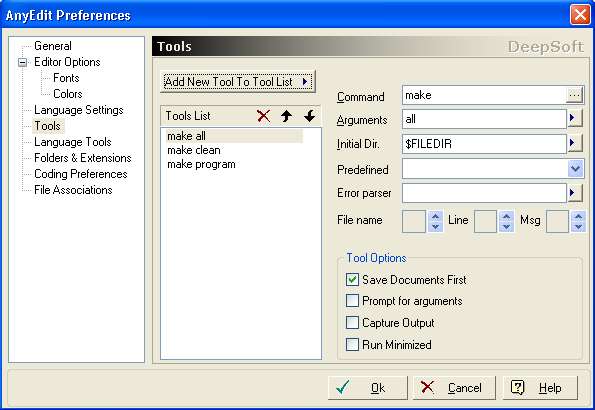
Download a text editor with syntax highlighting and the ability to execute user defined commands. AnyEdit is a good choice and it is free.
-
Connect the make commands make all, make clean and make program (see the next step 13 for make program) to the menu buttons. See this example for AnyEdit.
-
Once you have configured the editor just press the buttons in the menu and the compilation will be executed.
-
-
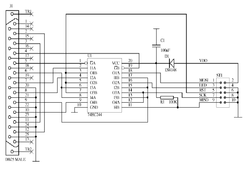
Connect the programmer to the PC port and microcontroller board. Make sure that the power supply for the microprocessor is switched on. Configure the makefile if you are not using the stk200-dongle. Read through the ISP Programmer chapter if not already done. Press the button associated with make program. You should see the programming LED flashing or beeing constantly on during the program cycle.
Note: The test.c example file just flashes the LEDs connected to Port C. You can start developing your program based on this file as all the neccessary header files for LCD, Servo, Uart and ADC are already included in both the makefile and the test.c.
![]()
Datasheets for the used hardware:
| Controller | AT90S8535.pdf |
| Photo Diode | bp104.pdf |
| FET | buz71.pdf |
| IR LED | sfh484_5.pdf |
| Board | simm100.pdf |